
There were several different Delco Remy ignition systems manufactured during the high performance muscle car era. This site is dedicated to the High Performance ignition systems from the 1960s and 70s manufactured by Delco Remy Division of General Motors Corporation, located in Anderson, Indiana.
I worked at Delco Remy for 23 years in the engineering laboratories and although I wasn’t able to spend a majority of my career in the ignition area, the inner workings of the various D-R ignition systems were my passion.
The ones I will try to focus on are:
- A) Transistor Ignition System – Contact Controlled and Magnetic Pulse (breakerless)
- B) CD Ignition System – Contact Controlled and Magnetic Pulse (breakerless)
- C) CD Ignition System – Indy Car System
- D) Turbine Ignition Systems (Constant spark systems)
- E) Unitized Ignition System (Pre-HEI, limited production)
- F) HEI System (pre-computer control)
A) Transistor Ignition Systems
Delco Remy manufactured a transistor ignition system that was used mainly on the high performance Camaros and Corvettes, both for racing and for street use. They were available for other models as well. Kits were also available so that they could be added to any 12-volt vehicle. Production of these systems took place from the early-mid 60s, thru the early 70s. On the contact controlled system, the breaker points become a low current switch, simply switching a transistor on and off. This greatly increased the life of the points since there was very little current being switched and no longer a small arc across them when they opened. These systems used a small amplifier box mounted on the car, along with a special ignition coil designed to work with the amplifier for increased output to the spark plugs.
Advertising brochure for the contact controlled (breaker points) system:


Here are the installation instructions that were included when purchased as an add-on kit, and the internal training brochure for understanding how the system worked:


The magnetic pulse system took it a step further, completely eliminating the breaker points and replacing them with a coil/magnet assembly and a trigger wheel attached to the distributor shaft. Other than the shaft, there were no moving parts to wear out, plus the trigger wheel was very precise and repeatable.
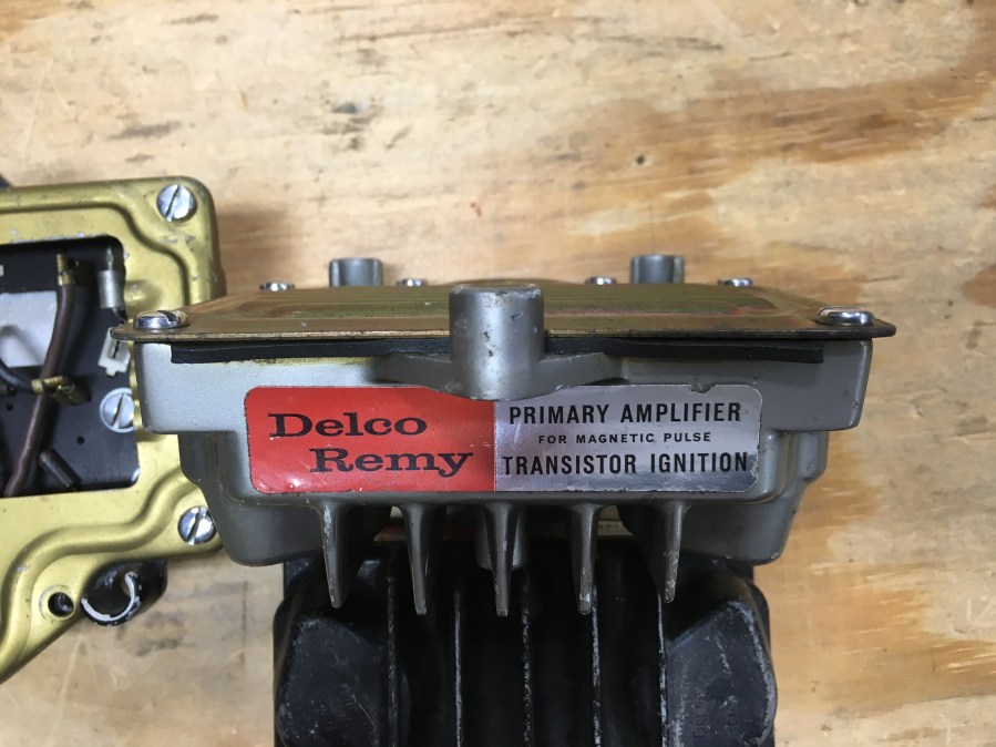
Here is the training brochure for the operation of the mag-pulse distributor and ignition amplifier, as well as a component layout for proper hookup:


Original engineering prints for the control amplifier:


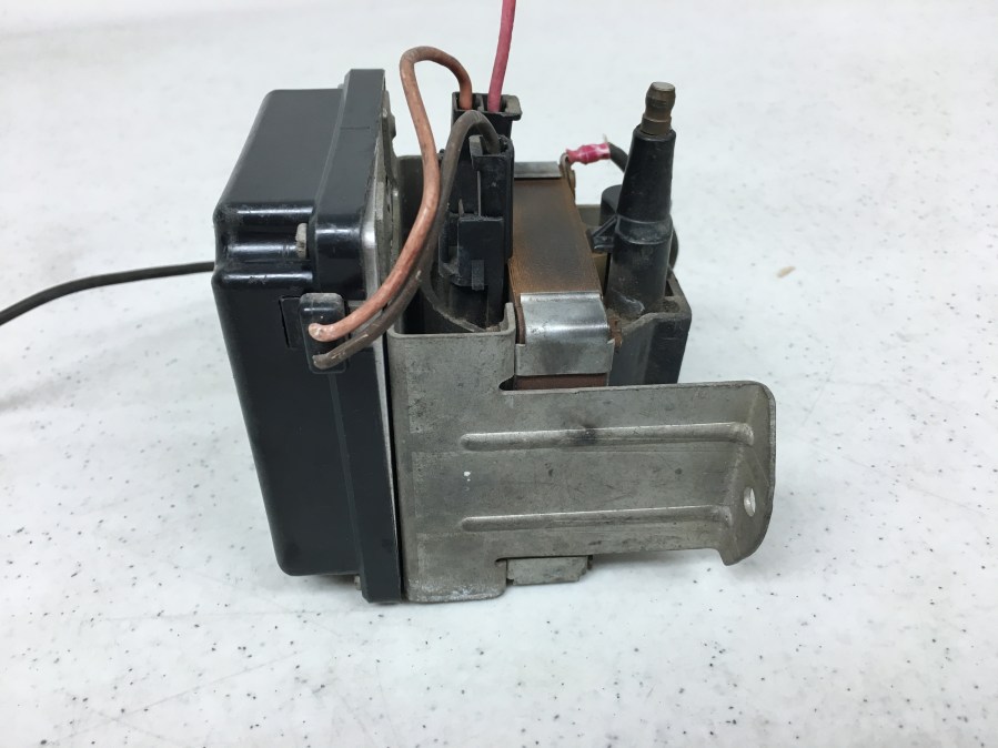
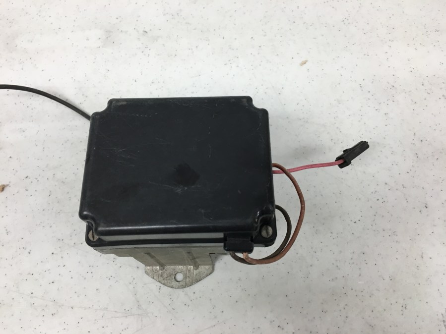
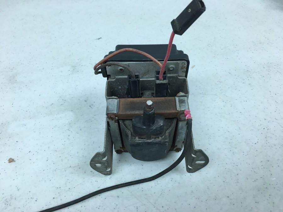
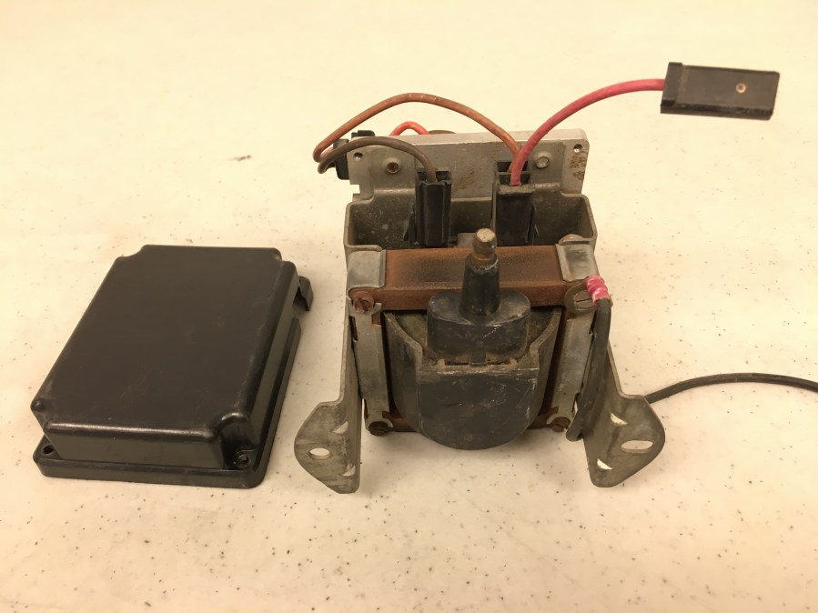
Original show sample TI amplifiers, saved from the scrap tub!! :
")
")
")
")
1115343 version that came with pigtail harness instead of case mounted connector:
")
")
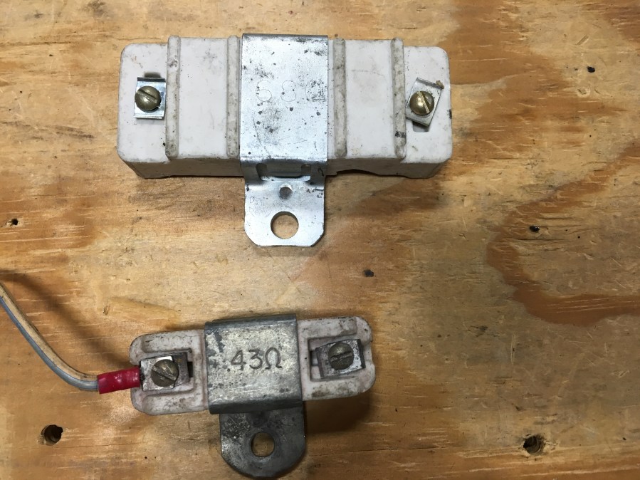
.43 and .68 ohm resistors that came with add-on kit:
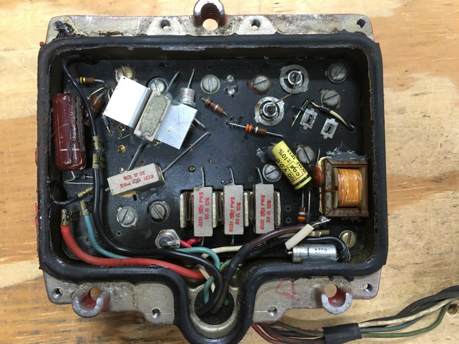
Contact controlled circuit board and very early design mag-pulse circuit board:
")
")
")
")
B) CD Ignition Systems
Delco Remy manufactured several models and designs of Capacitor Discharge ignition systems for various automotive applications, and even some for military vehicles! Although they were never that popular or well known, they were optional equipment on some of the performance oriented Pontiacs, Oldsmobiles, and a few Chevrolets in the 1966-69 time frame. I always felt that this was the ultimate ignition system for any special high performance engine (high compression, high RPM, solid lifter, big cam), because it eliminated the “loading up” of the engine from slow speed, around town driving. I had a 1969 Z/28 Camaro back in the day that had this type of engine in it. After driving around town for awhile, when you tried to rev it up it would misfire until you took it out on the highway and “blew it out” by going thru the gears aggressively. The CD ignition virtually eliminated the need for this because even with build up on the spark plugs, the ignition system blasted right thru it due to the fast rise and discharge time of the capacitor. Along with the specially designed ignition coil for this system, the discharge across the spark plug was so quick there was no time for ignition energy to be bled off thru spark plug deposits, causing a misfire.
The Delco Remy CD Ignition System was manufactured for both contact controlled and magnetic pulse applications. I have only seen the contact controlled version as an add-on kit. I have never seen or heard of it as an option on a new vehicle.
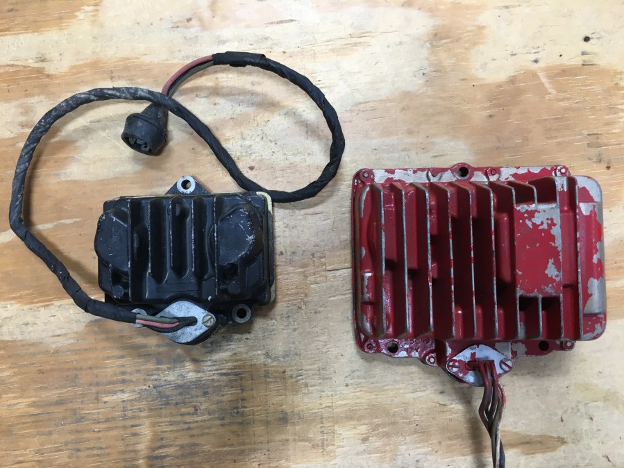
Early design experimental CD amplifier from early-mid 60s:
")
")
Experimental CD case was similar in design to TI case, kind of a larger version:
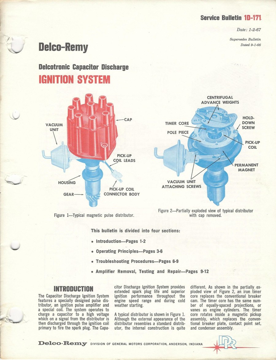
Contact controlled CD Ignition internal training brochure and installation manual:


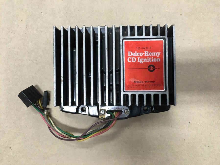
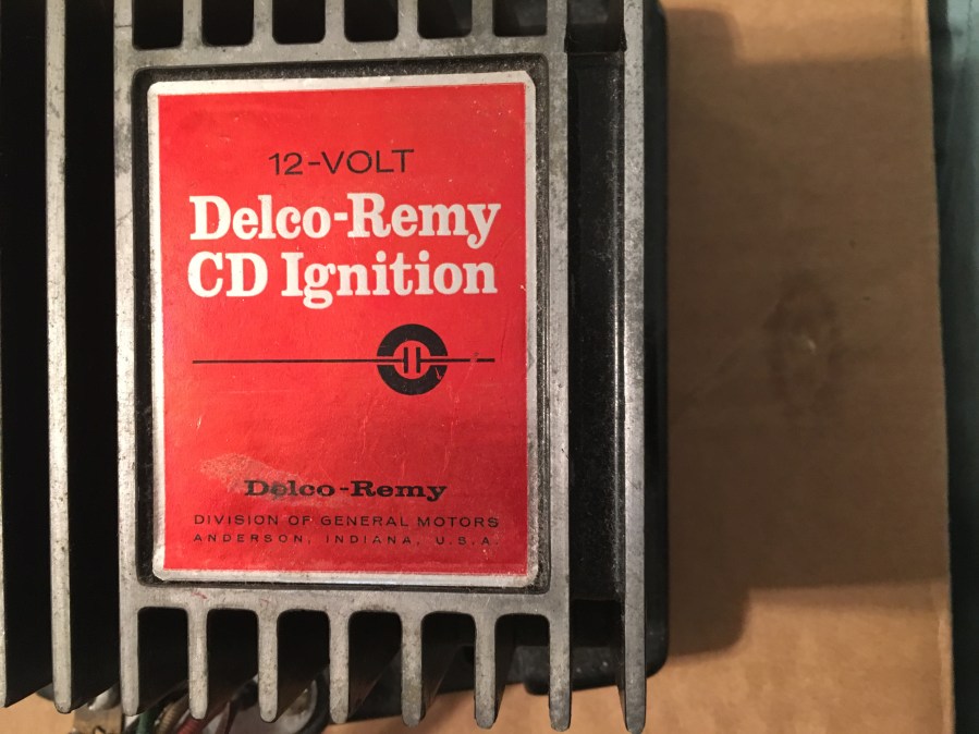
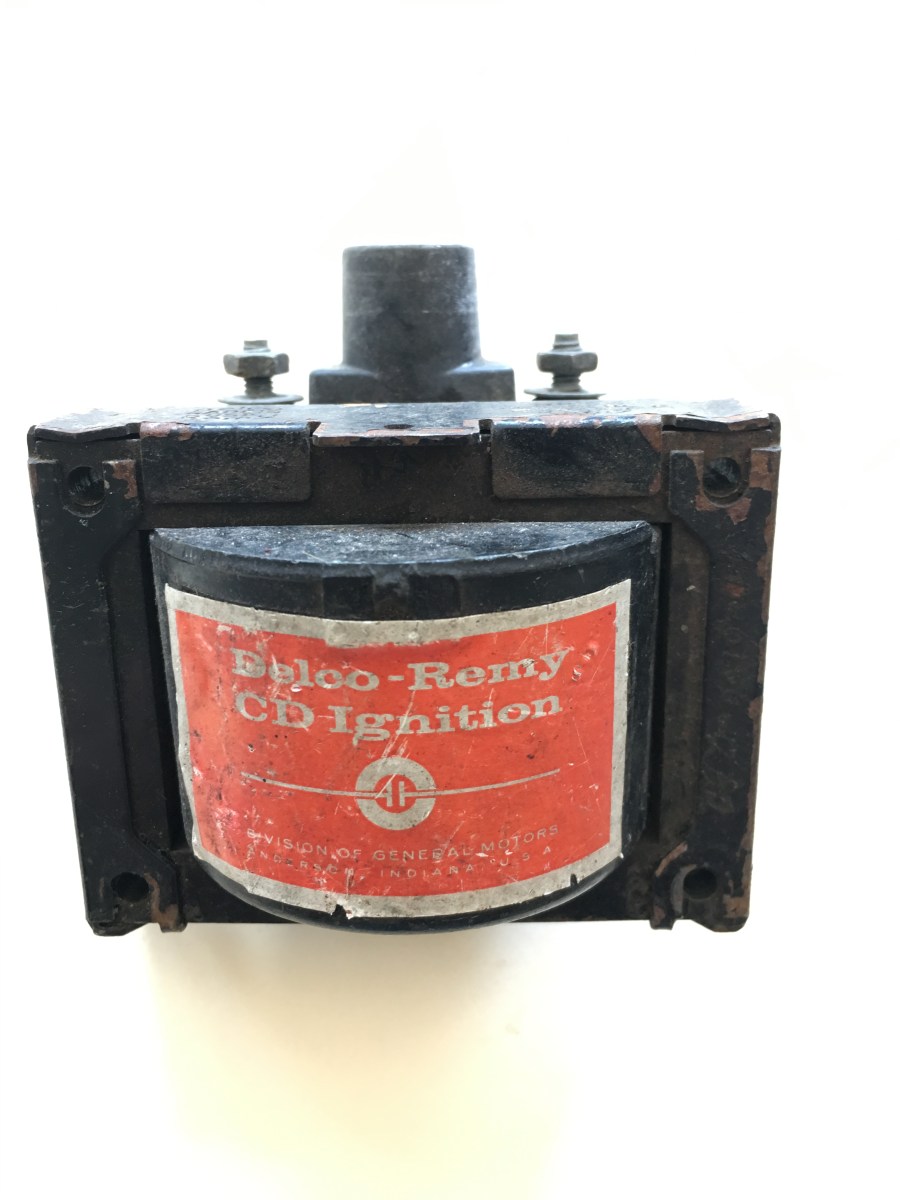
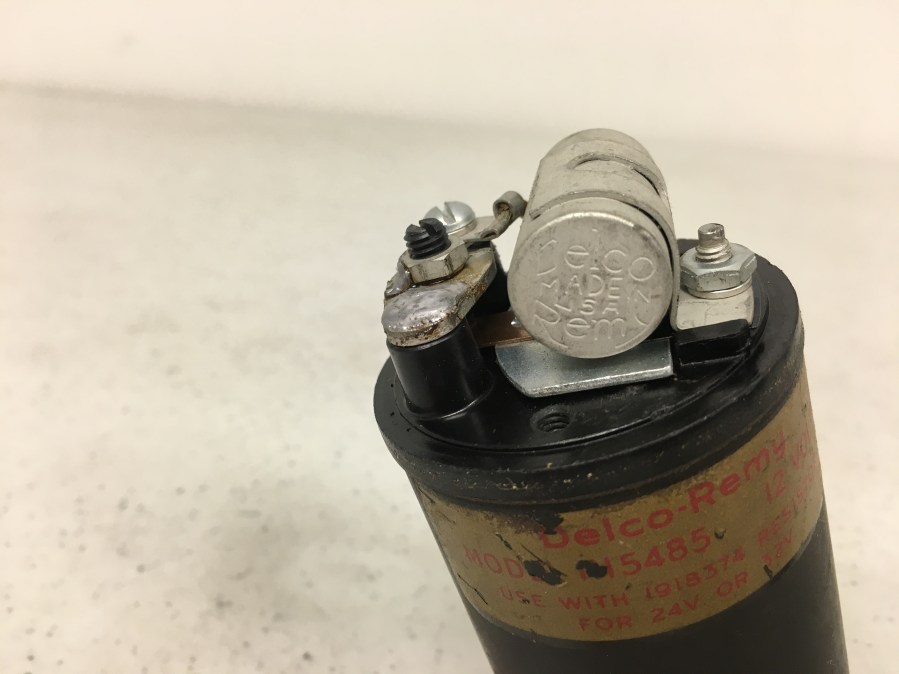
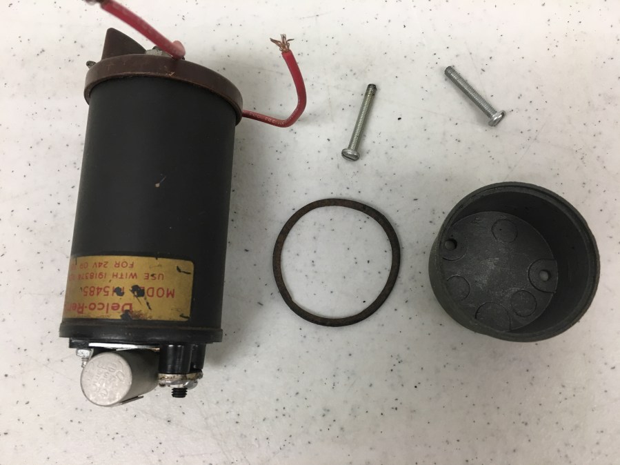
Contact controlled CD ignition amplifier and label closeup:


The cream of the crop ignition system for the late 60s, and where most of the resources were applied was the Delcotronic CD Ignition System. This was the magnetic pulse (breakerless) system with the red distributor cap and red ignition coil that was optional on some high performance Oldsmodiles, Pontiacs, and Chevrolets. For the Oldsmobiles they were labeled as “UHV” for ultra high voltage, for the Pontiacs and Chevys I think they were just labeled as “CD”. This is the system I ran on my 69 Z/28 Camaro with the high winding, solid lifter 302 engine, and just loved it! No points to deal with, and maximum ignition output whether you were trying to start at 10 below zero or running at 7000 RPM! The performance was unsurpassed by any other ignition system around at the time. These systems never really caught on in popularity, probably due to initial cost and a short life span due to the coming emissions laws that forced lean carburetor mixtures. Due to the fast rise time and short spark duration, these systems needed the normally richer fuel mixtures of the 60s to operate properly. I think by 1970 these systems were done. However they would make a resurgence in about 15 years as the ignition system used on several Indy cars in the mid-80s!
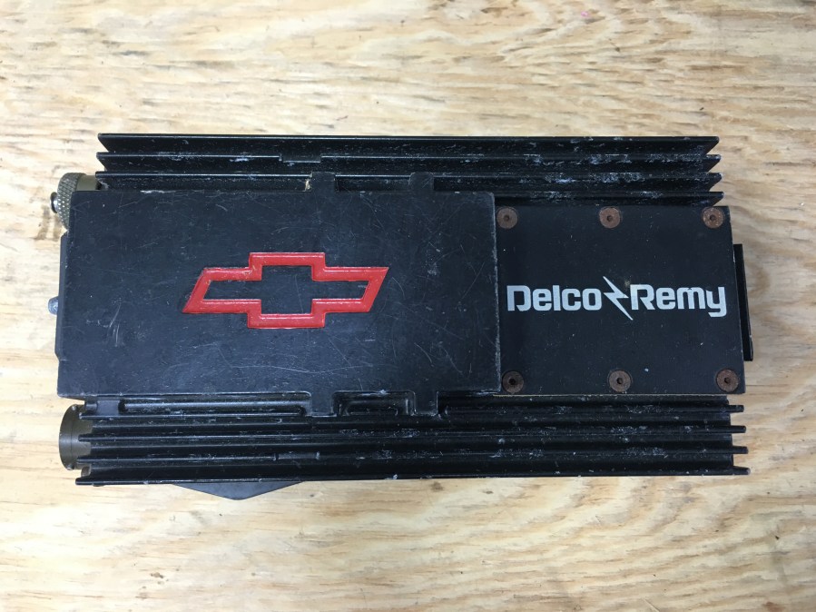
The gem of my collection! This show sample Delcotronic CD Amplifier was salvaged from the scrap tub! It has a few minor chips from being tossed out as scrap, but all in all it’s a real beauty with a high gloss enamel paint job, special label, chrome back plate with clear plastic window to see all of the internal parts, chrome screws and polished heat sinks!

Lots of advertising brochures and information for these systems:


Oldsmobile version:


Training brochure:
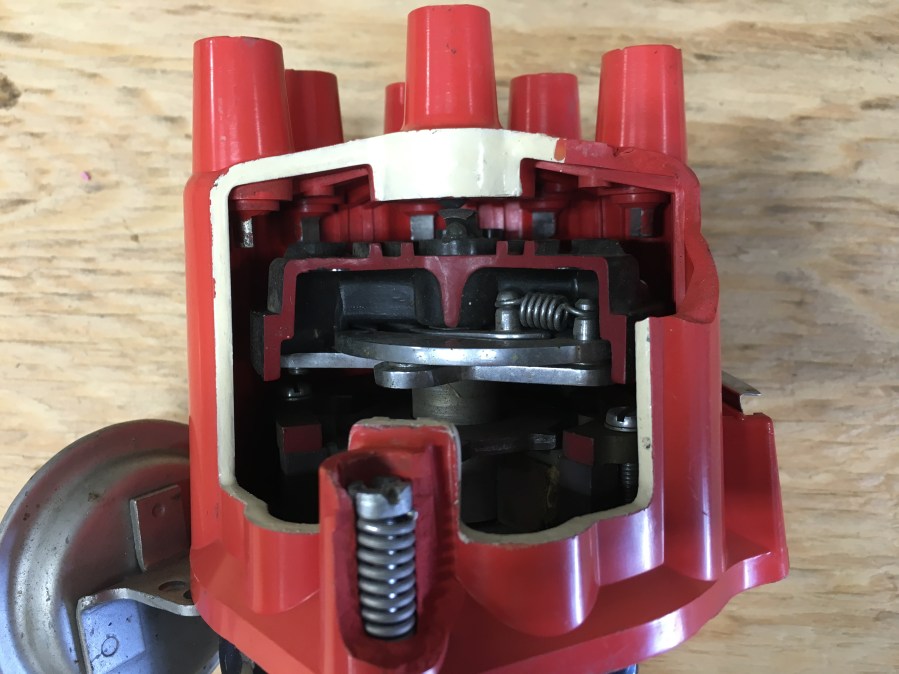
Show sample cut away distributors for the CD system, showing the internal parts:


Original Pontiac CD ignition system distributor:
")
")
Engineering prints 1115010 model:


Engineering prints 1115016 model:


1968 Phase III 427 Camaro with Delco Remy CD ignition system on magazine cover:

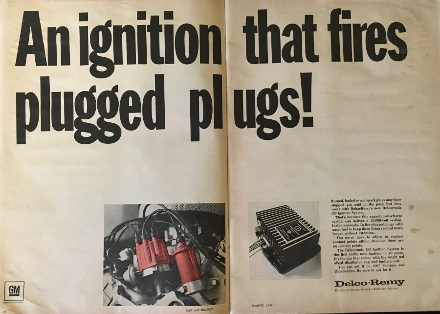
Magazine ad from 1967 for Delco Remy CD Ignition System:
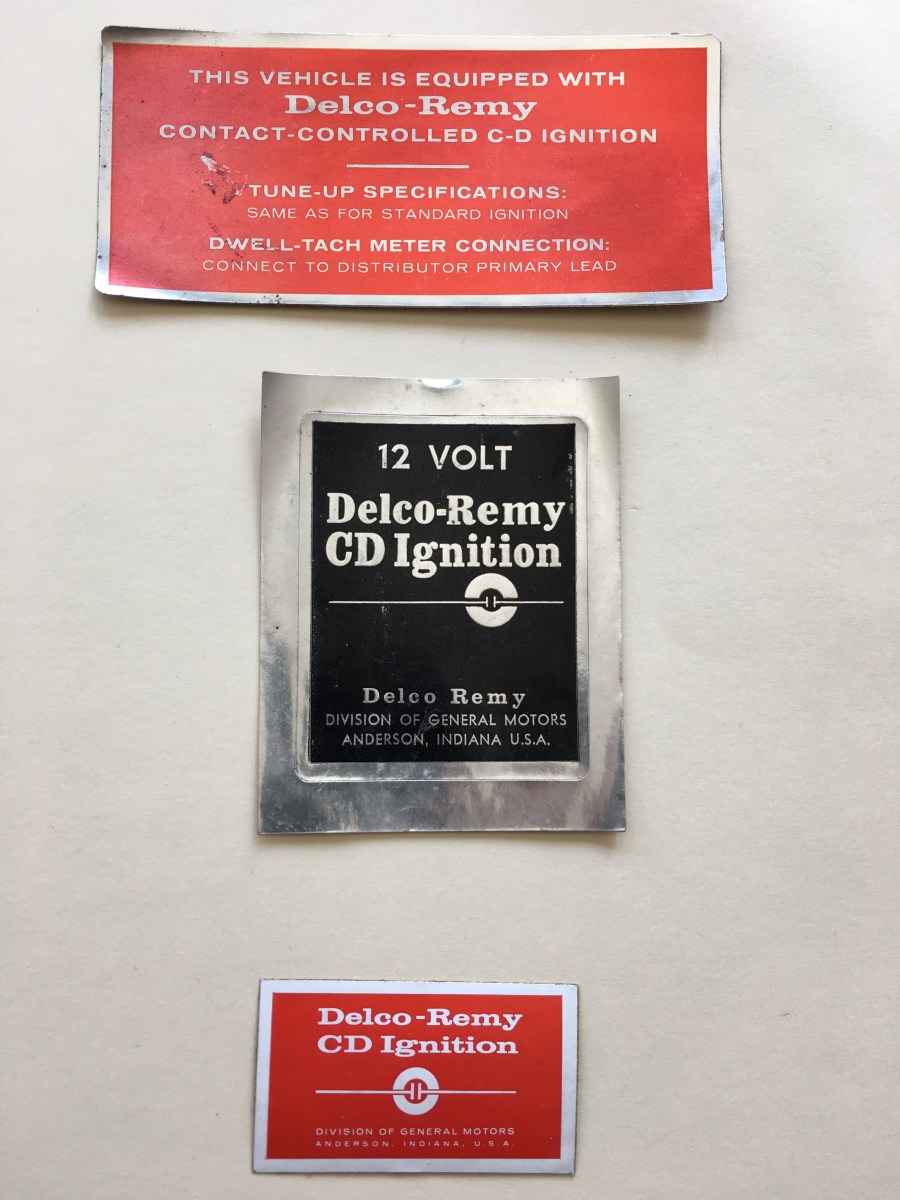
Closeup view of various production labels:


Some original Delco Remy CD ignition labels that I have. The top one was probably used on test vehicles so a mechanic knew what he was dealing with. The middle label was a later, generic label for the various amplifiers. The bottom label is for the epoxy (transformer style) CD coils.
The oil filled ignition coils used with the CD systems were painted red making them easily identified, much like the distributor caps. Some coils are embossed with “CD” while others simply have “12-V” embossed in the case. A non-oil filled coil was also designed for use with the CD systems. This coil had various brackets designed for it so that it would fit in traditional oil filled engine mounted coil brackets.
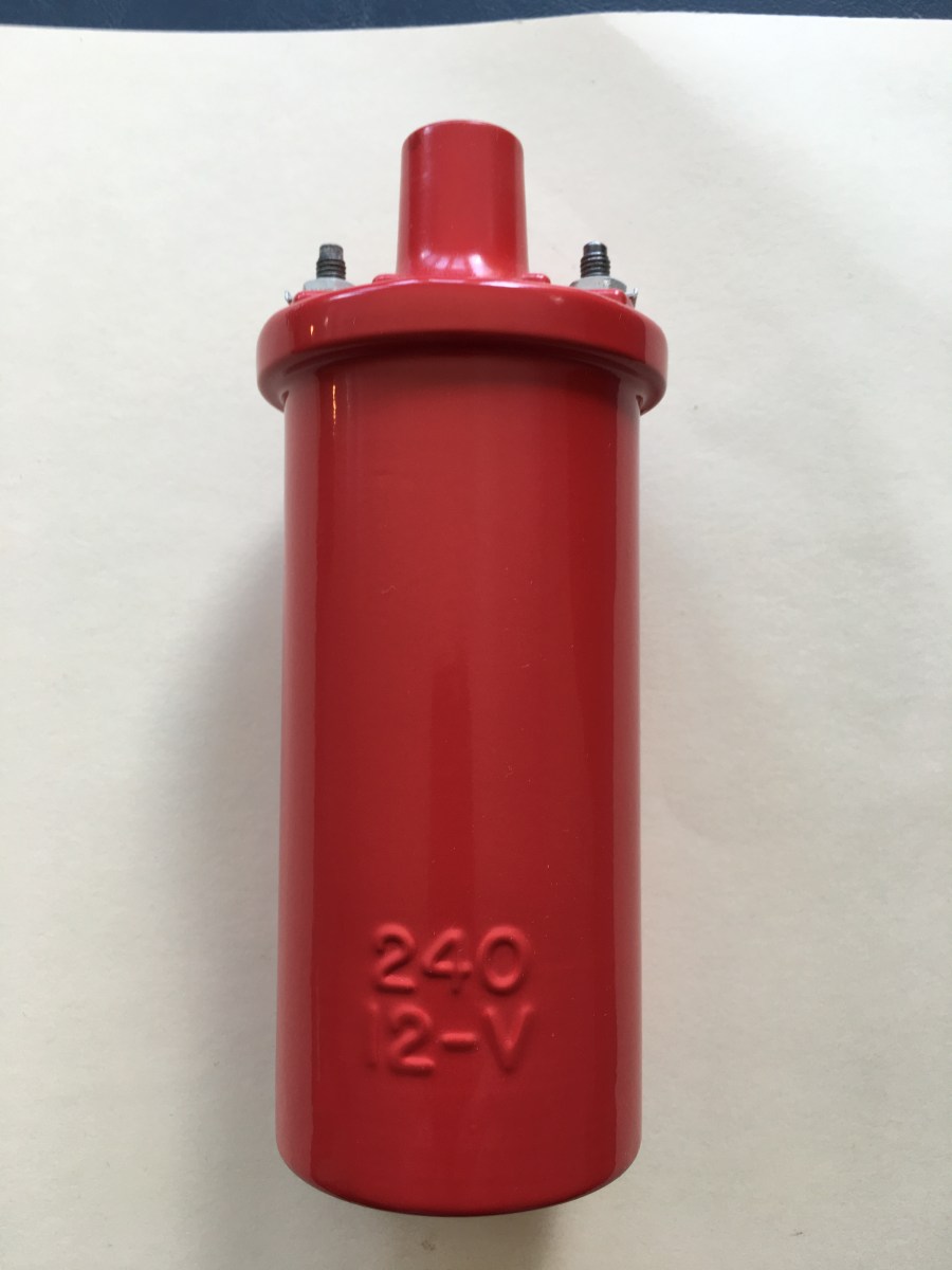
CD coil 1115240 Coils are usually embossed with the last three of the part number.
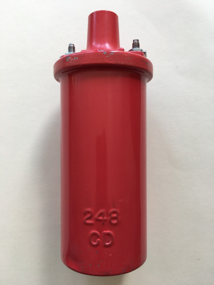
CD coil 1115248. Probably the most common one found. This was a revision to the original 1115240 coil.

299 CD coil. Seldom seen, not sure of original application.
CD coil 1115406. This is an epoxy filled coil instead of the more common oil filled coil. Usually came with an adapter so it could fit in a standard engine mounted coil bracket.
Pontiac Ram Air V engine and the redesigned Delco Remy CD Ignition System for it
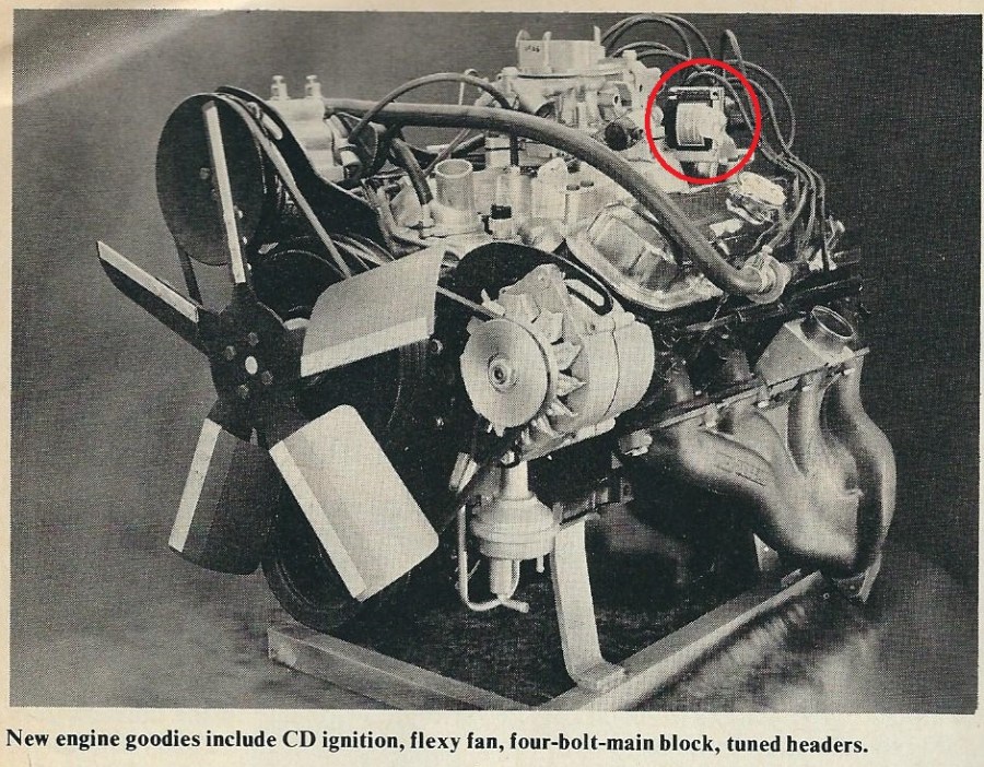
During the 1969 model year Pontiac was developing a new tunnel port engine known as the Ram Air V. The engine was to be available in a few displacements, the main ones being a 303 CID for the popular Trans Am racing series, and a 400 CID for the street/strip scene.
Pontiac RA-V 303 CID engine picture from a 1969 magazine article. I have highlighted the Delco Remy CD Ignition coil (1115406) mounted on the engine:
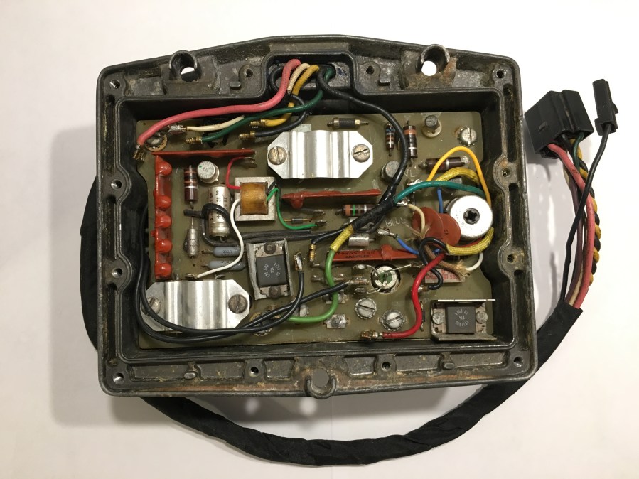
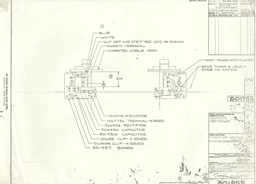
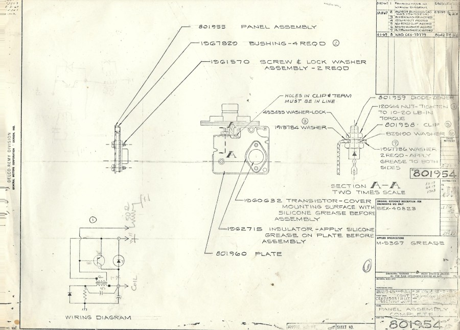
Around this same time period Delco Remy was working on a redesigned CD ignition system that was to be used on the new Pontiac engine program, and possibly as a replacement for the existing CD systems. I don’t know if this system was specifically developed for the Pontiac engine or not, but it appears that Pontiac was going to be the first customer, at least. Two production part numbers were assigned to these new CD units, 1115345 and 1115346. The only difference between them was the rev limiter setting. The rev limiter “chip” in the 1115345 unit was set at 7000 rpm. I don’t have the print for the rev limiter “chip” used in the 1115346 unit so I don’t know what the setting was.
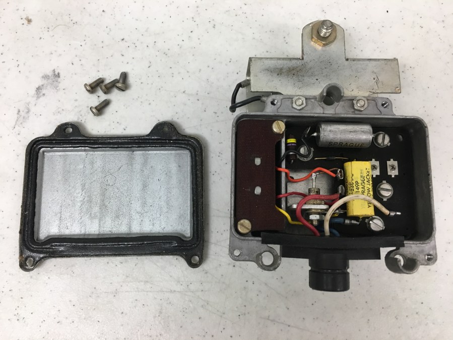
There are probably a few of these units around but I believe they are quite rare. I am fortunate to have one (1115345) and it still works just fine!
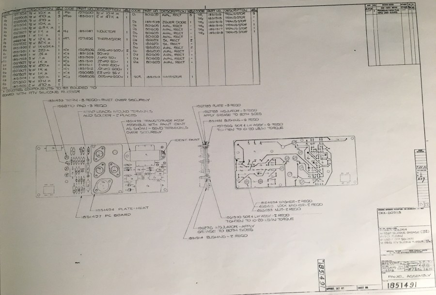
Engineering prints for amplifier 1115346, dated 3/24/69:
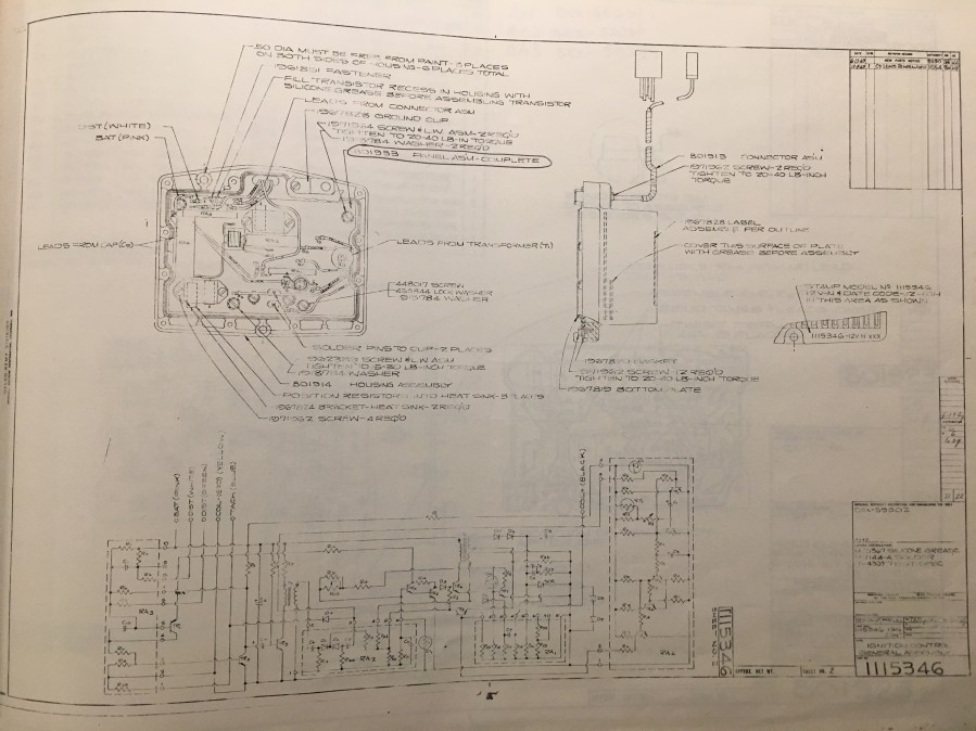
If you look at the circuit board panel prints 801923 (used in 1115345 amp), and 801934 (used in 1115346 amp), you can figure out that the only difference is RA4, the rev limiter “chip”. Every other part is identical between the two amplifiers.
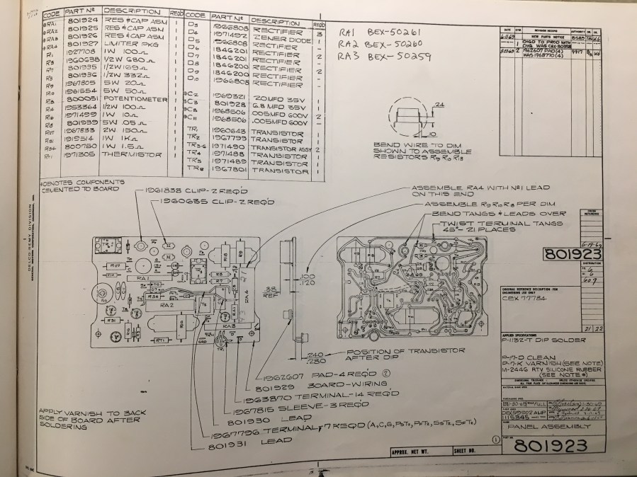
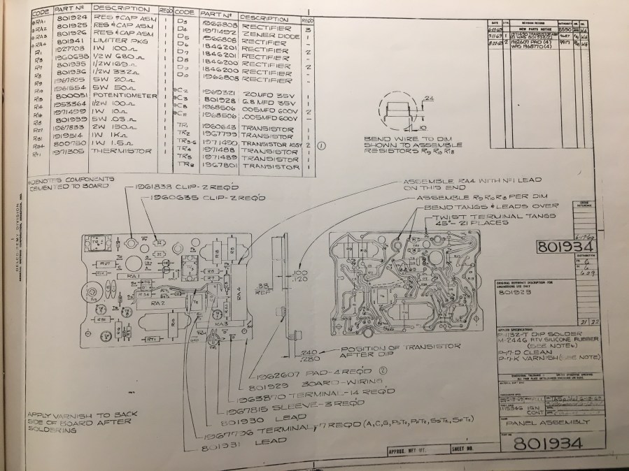
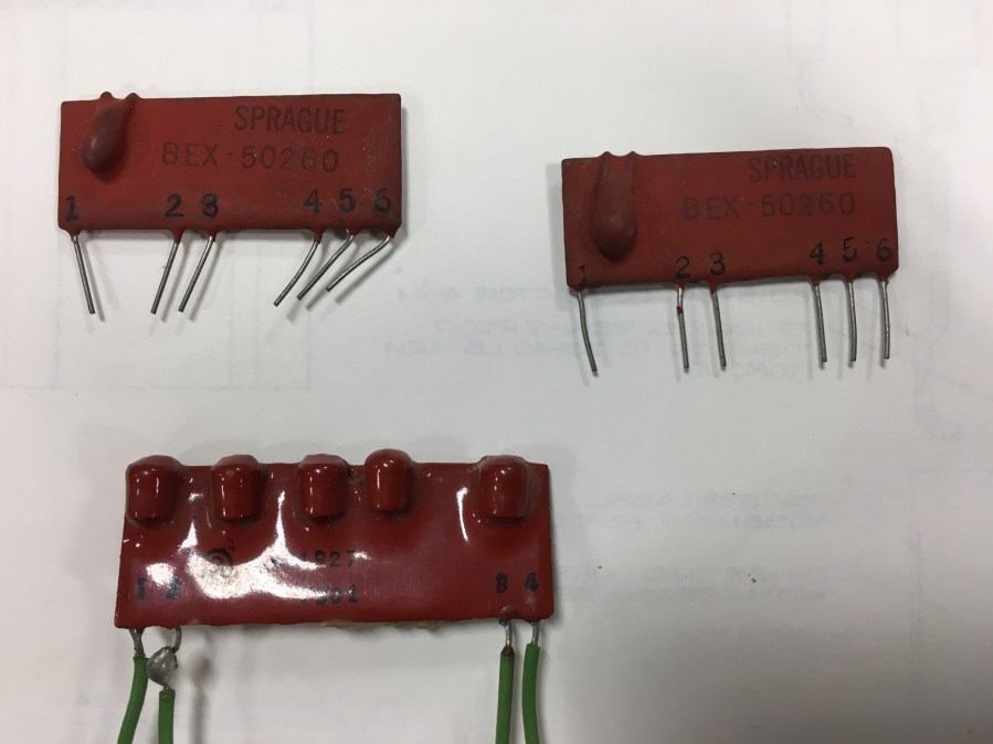
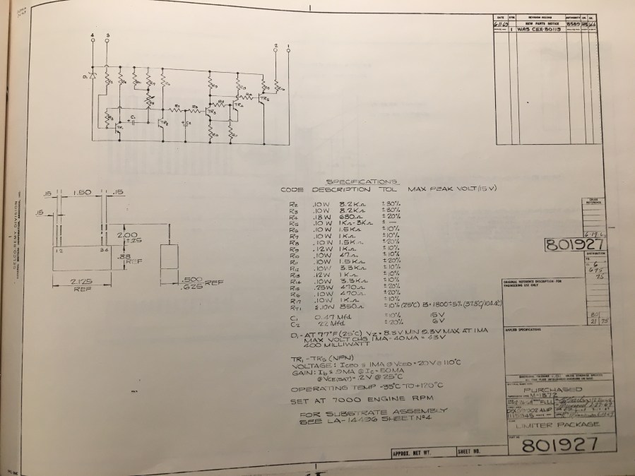
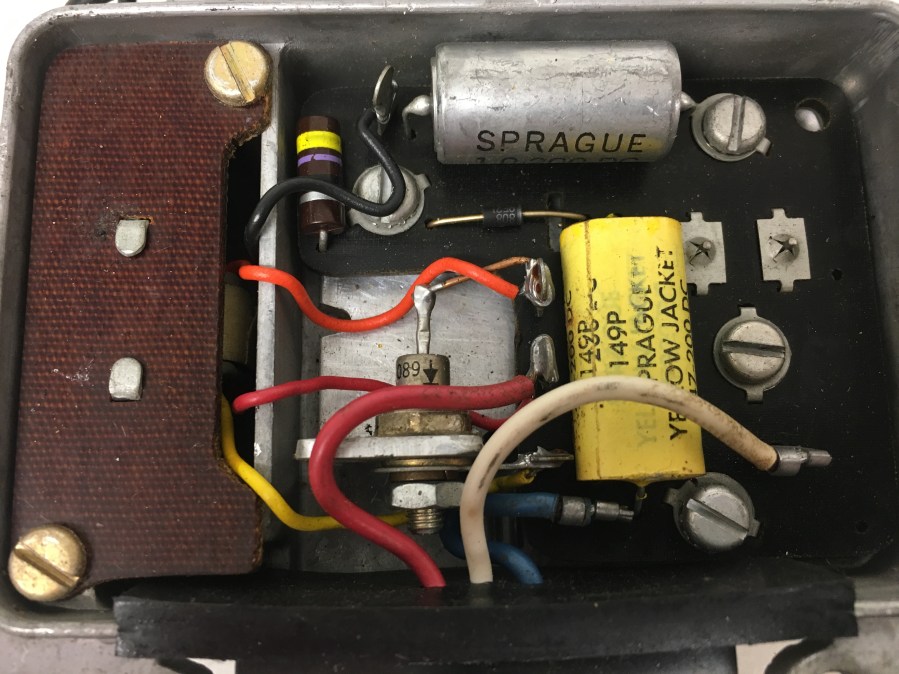
These were the first GM ignition systems that made use of what I call early IC chips. You can see that they used four of them in these (the orange colored straight devices). The engineering prints refer to them as “resistor & capacitor assemblies”, even though some of them have more than just resistors and capacitors. Basically they were components assembled on a substrate and then coated in the orange “stuff” for protection. Just as in later electronics, this saved valuable circuit board space. The vertical one on the far left of the actual amplifier pictured up above is the rev limiter chip, and the blobs you see on the top edge are transistors.
Up close view of a few of the extra “chips” I have:
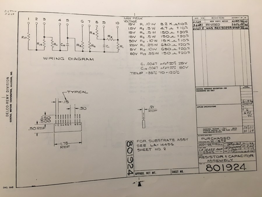
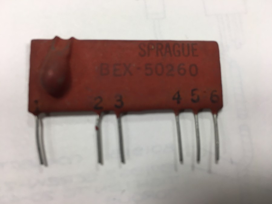
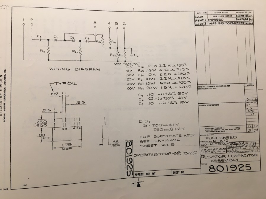
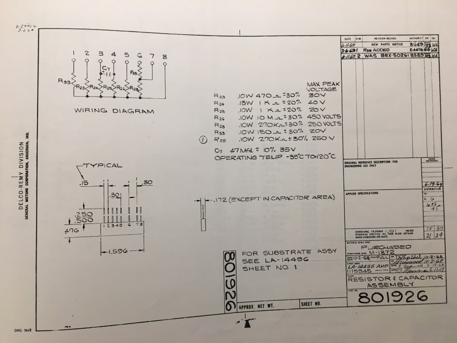
Close up of the “limiter package” chip, part number 801927, followed by the engineering print for it. The designation 7001 is the value in hundreds (700) and how many zeros follow it (1), which equals 7000 rpm in this case.


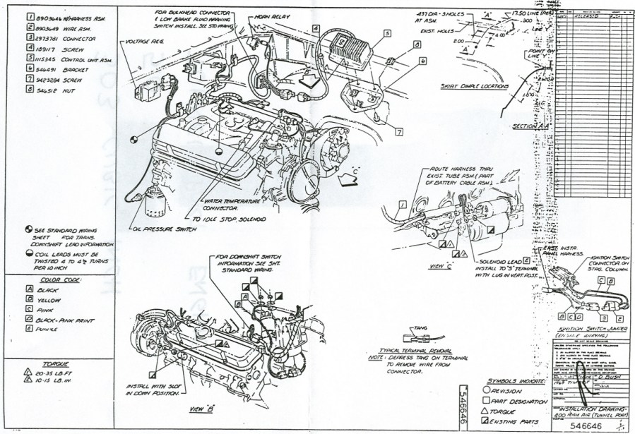
Pontiac RA-V production assembly print calling out the bracketry and location for mounting the 1115345 amplifier! (#5 in the far left column)
All in all, a bunch of super-cool stuff that was never to be due to the upcoming tightening emissions laws and the big clamp down on performance cars in general.
Military CD System
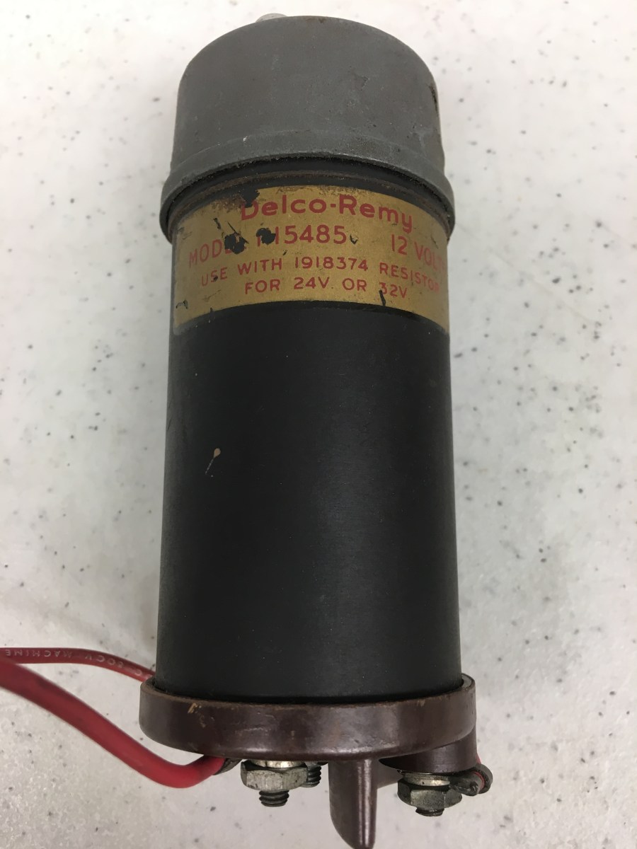
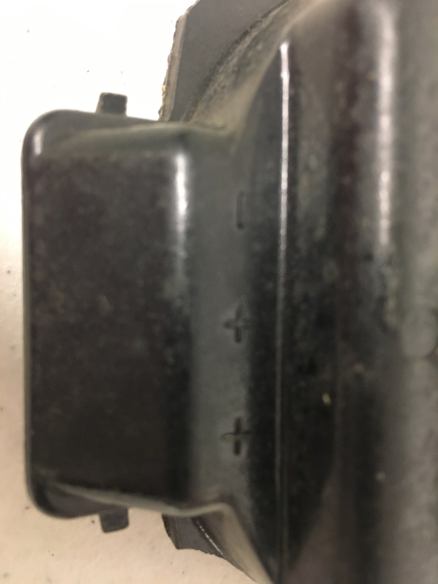
Around 1970 Delco Remy designed and manufactured a CD ignition system for the US military. I don’t have any of these units, but I do remember them. The CD case was about 50% longer than the regular production units made during 1967-69. I remember the spark plug wires were completely shielded with a special hookup at both the spark plug end and the distributor cap end. The towers on the distributor cap were threaded and each plug wire had a threaded sleeve that attached the wire to the cap, much like the end of a speedometer cable. The CD amplifier and ignition coil were both painted in typical military olive drab green. I wish I had an amplifier to show, but I do at least have a military CD coil.
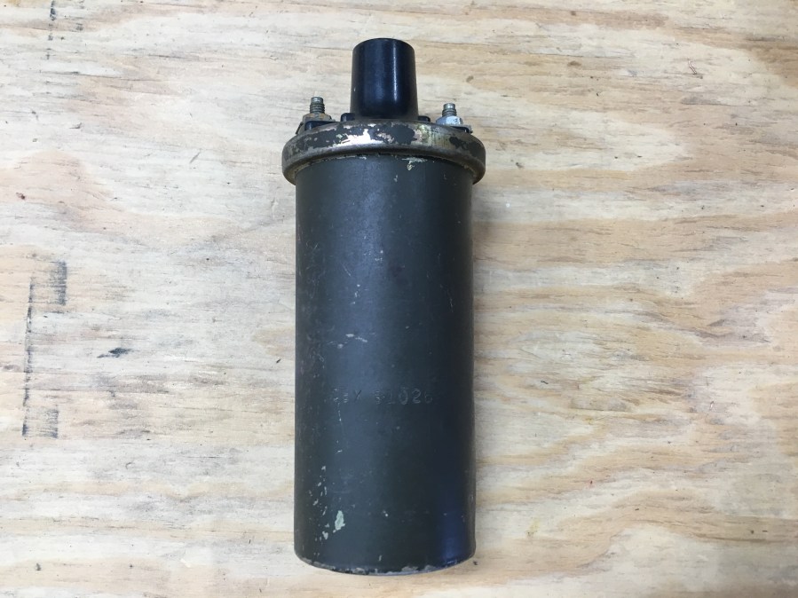
It’s hard to tell from the picture that it’s olive drab, but it is.
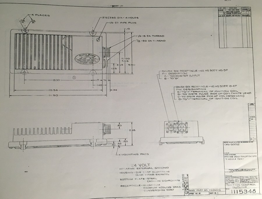
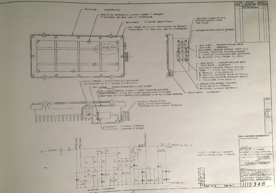
Original engineering drawings of the Military CD amplifier:
I don’t know how many were manufactured or sold, but it was an impressive looking system. Although rare and somewhat unknown, this would not be the end of this design!
C) Indycar CD System
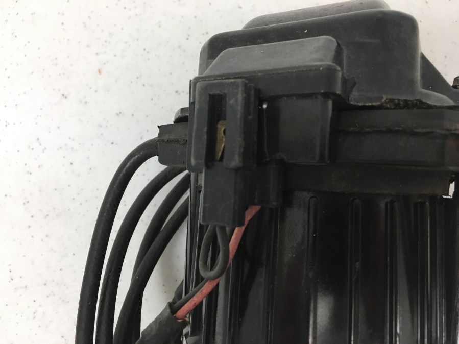
Fast forward to the late 80’s, early 90’s and Delco Remy was involved in the Chevrolet Indycar racing program, supporting parts of the electrical system, including the ignition system. It was determined that a CD ignition system would be suitable for this powerful, high revving engine. The long forgotten Military CD system was revived for the Indycar race program! The same basic circuit design was used with just some minor updates and the latest technology (early 90’s) components. A special case was designed which contained not only the electronics but also the ignition coil.


All of the wiring was high quality teflon insulated and the hookup to the unit was with a Mil-spec connector. The hookup to the coil was basically a spark plug wire with high voltage boot pushed thru a grommet and onto the high voltage tower.
As mentioned, other than some minor circuit updates, this was the Military CD system repackaged!
D) Turbine Ignition Systems (also diesel start assist)
Turbine engines require spark ignition for starting only, so the ignition system sees only intermittent duty. Spark timing is not an issue when starting a turbine engine so these ignition systems emit a constant spark stream to get the engine started. From a personal perspective, these work great for starting my small. pulse-jet engine!
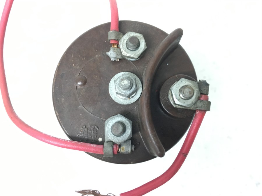
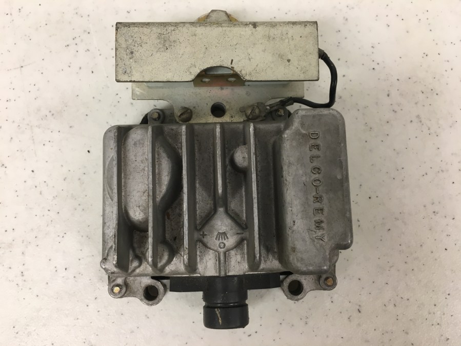
This earliest Delco Remy system is not referred to as a turbine igniter, but rather a diesel engine start assist. Either way it fits the category so here it is.
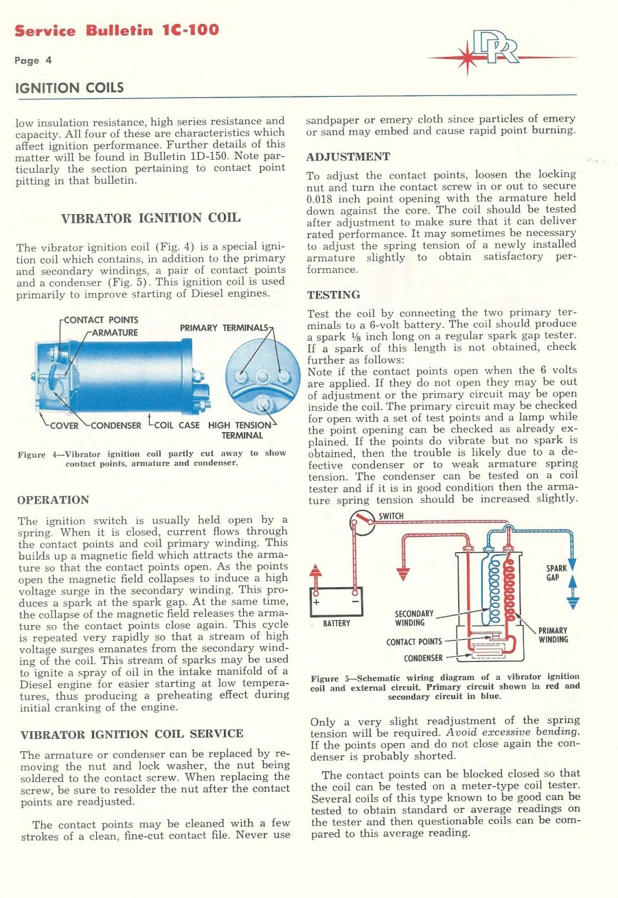
Vibrating contact constant spark igniter
Simple operation really. A set of contacts is in series with the primary winding of the ignition coil. Contacts are normally closed. Apply power, current flows thru primary creating electromagnetic effect which pulls contacts open disrupting current flow, causes field to collapse across secondary of coil creating spark. Since field has collapsed, contacts close, starting process all over again! This is where the “vibrating contact” term comes from.
Info from DR service bulletin:
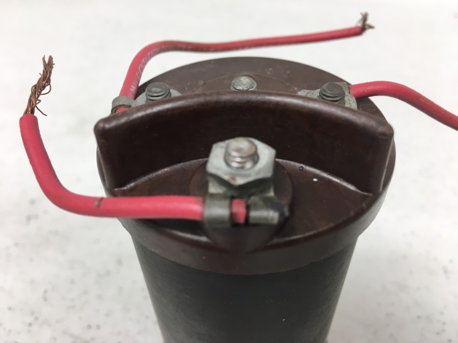
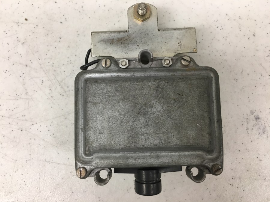
Various views:
Just add power and ground and away it goes!
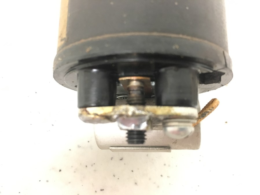
Notice high voltage separator:
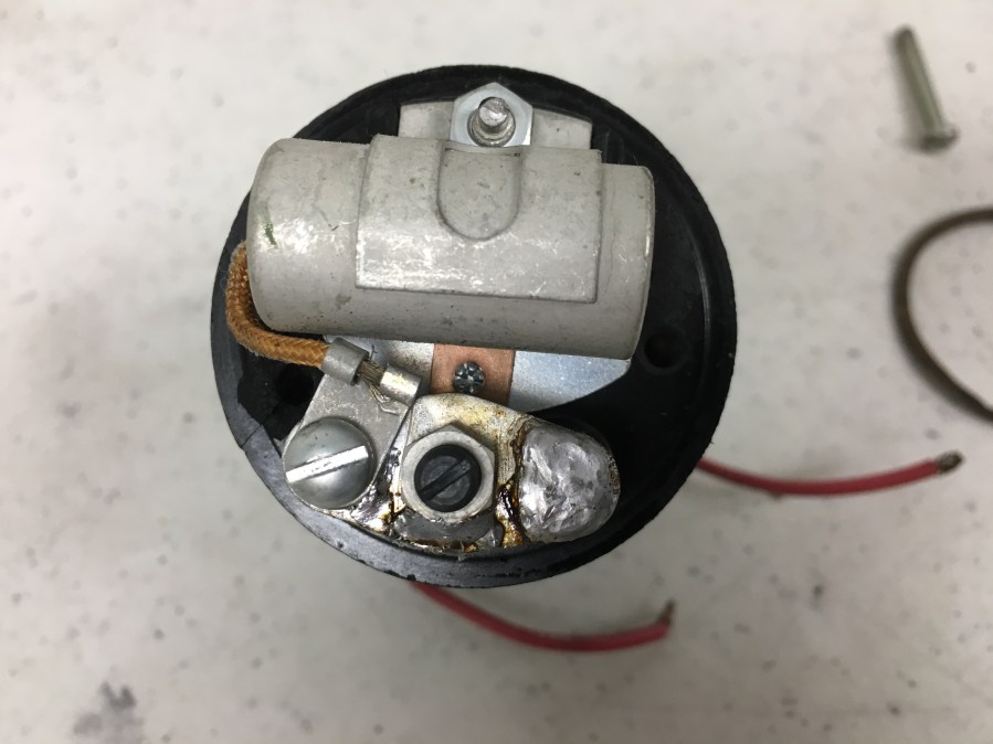
Contacts:
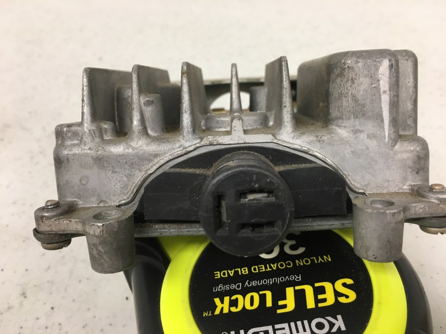
Transistor Ignition-era Turbine Igniter System
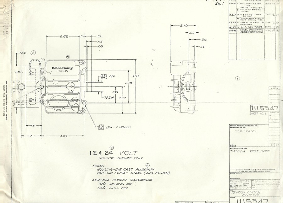
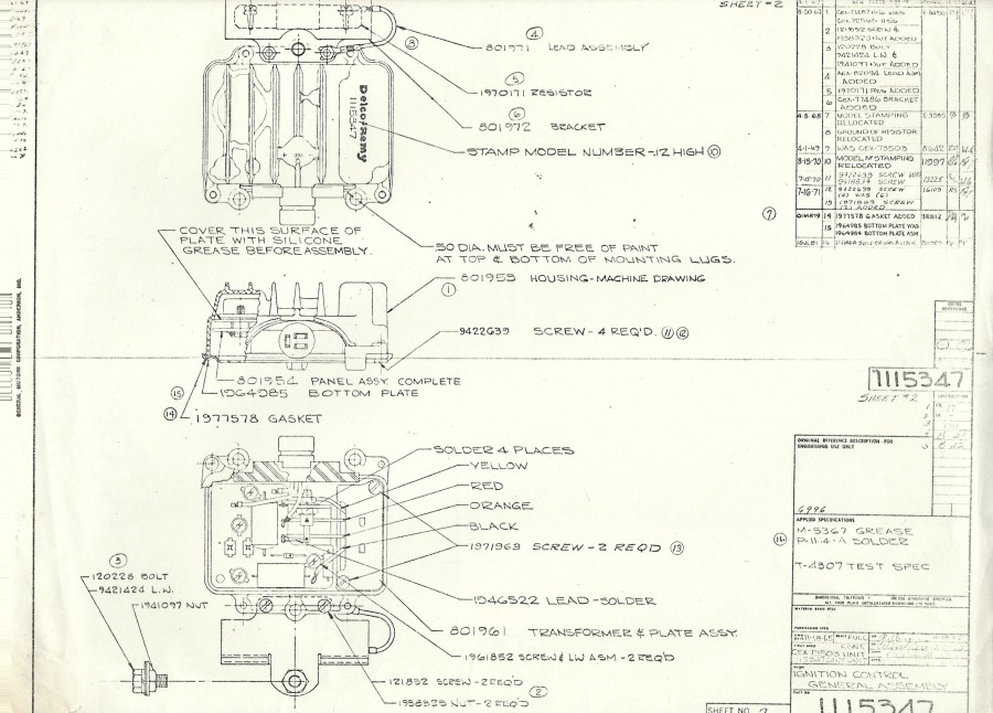
A turbine igniter system was designed around the same time as the famous Delco Remy transistor ignition systems of the 1960’s (K66). The part number of this system was 1115347. The case looks like it was also used for one of the transistor voltage regulator models.
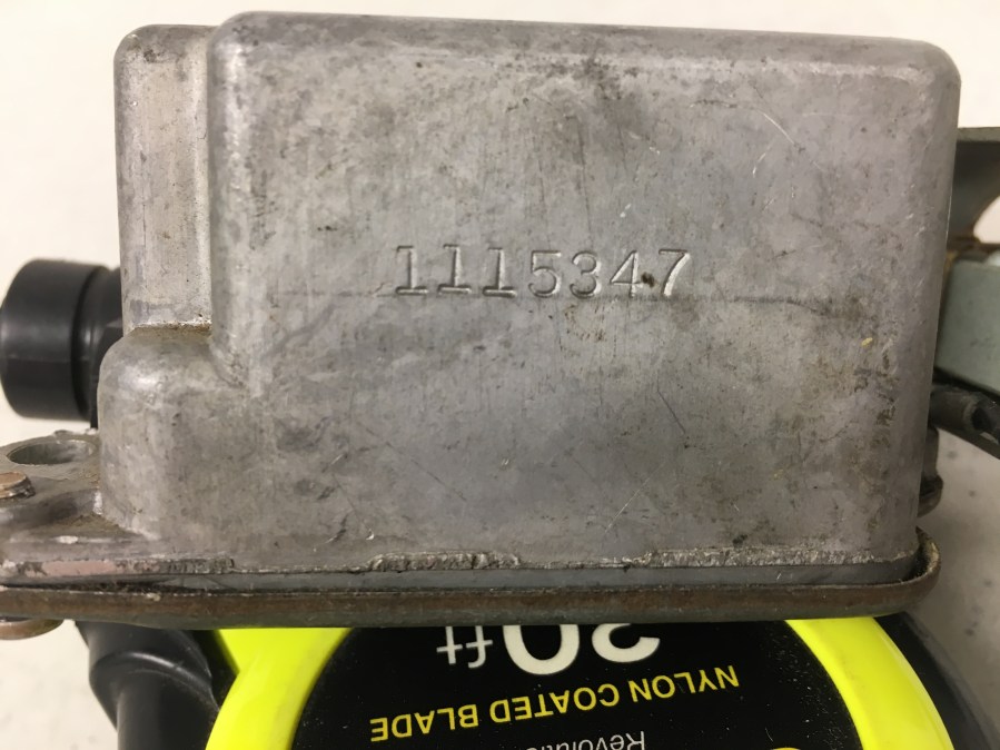

Original engineering prints for 1115347:
Inside views:
HEI style turbine igniter
The last and best of the bunch was the turbine igniter from the HEI era. I do not know if this was a production piece or not. There is no part number on it so I could never look up any engineering prints. If anybody has more info on this unit please let me know.
It used a separate mount HEI ignition coil, with a plate and cover for the electronics, all held together with a stamped steel mounting bracket. Simple, but a great design!
The electronics. An oscillator triggering into an HEI module; doesn’t get much simpler than that! And this thing will throw quite an arc!
Just add 12 volts and ground and make sure you have a good spark gap setup or it will bite you!
E) Unitized Ignition System
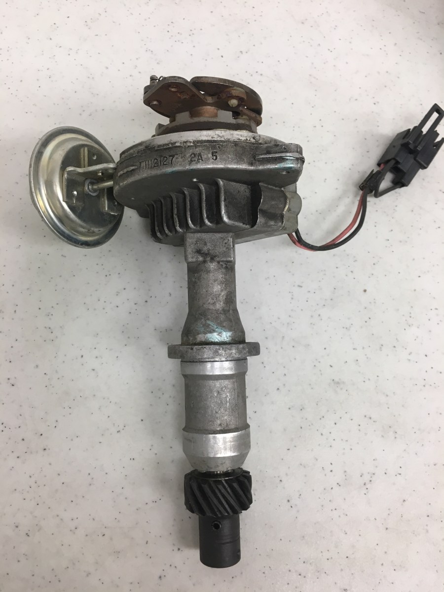
The Unitized ignition system was the forerunner of the HEI ignition system and was the first production attempt at having the complete ignition system combined in one unit (distributor, coil, and plug wires). These systems were an up-option in 1972-73 on Pontiac high performance engines.

This system used a distributor mounted ignition module with integrated electronics, a huge gain over the earlier transistor ignition separately mounted amplifier box with its performance limiting add-on resistors.
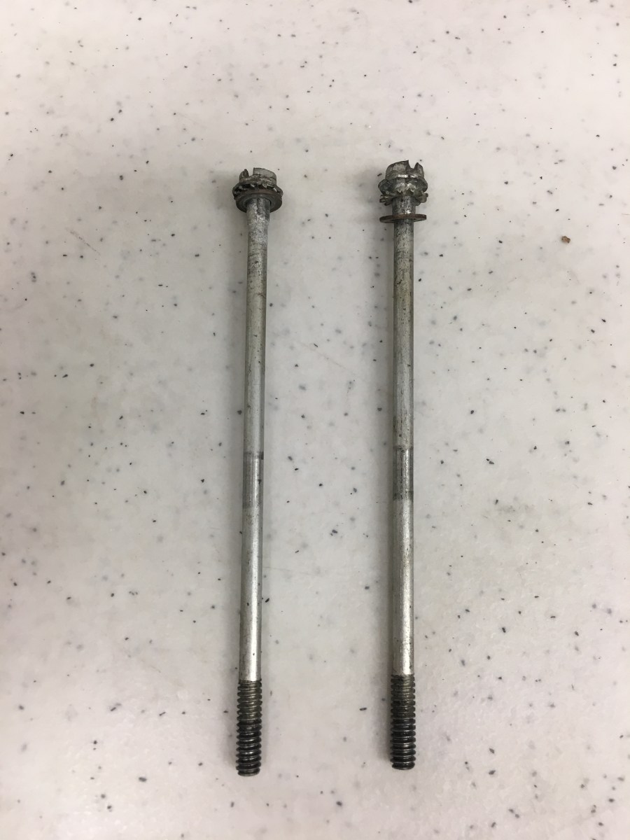
The various components of the Unitized system consisted of the distributor, the cap, the spark plug wire assembly, the ignition coil, and two long thrubolts that pulled it all together.
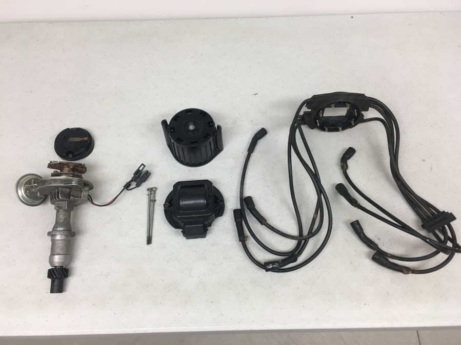
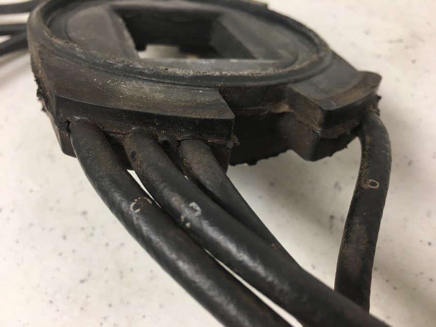


The spark plug wire assemble also included the “tower” that the rotor fired to. One problem with this arrangement was that if one plug wire failed, you changed the whole assembly.
Plug wire assembly
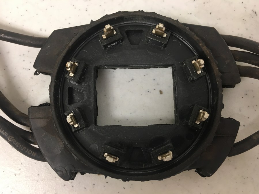
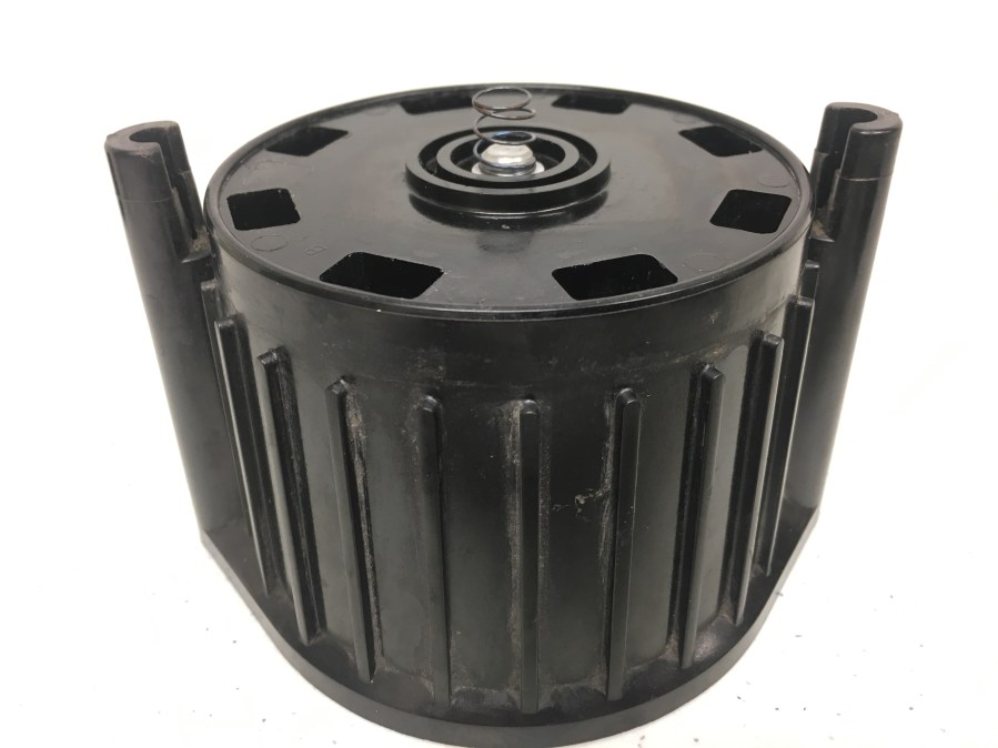
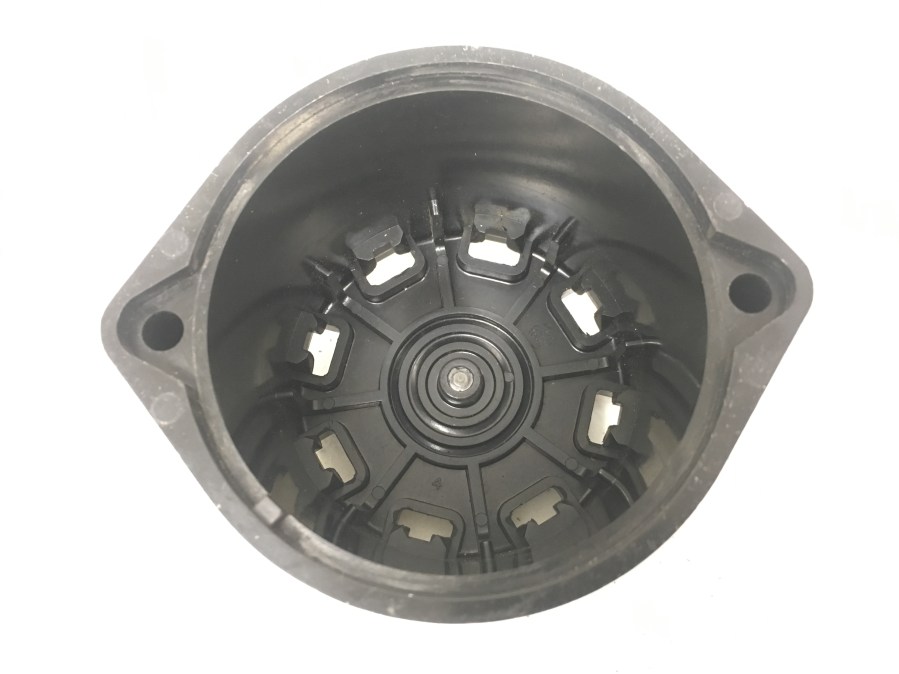
Cap
Cap and plug wires assembled together

Plug wires had cylinder number on them for proper installation

Potted coil assembly topped it off
Bottom of ignition coil

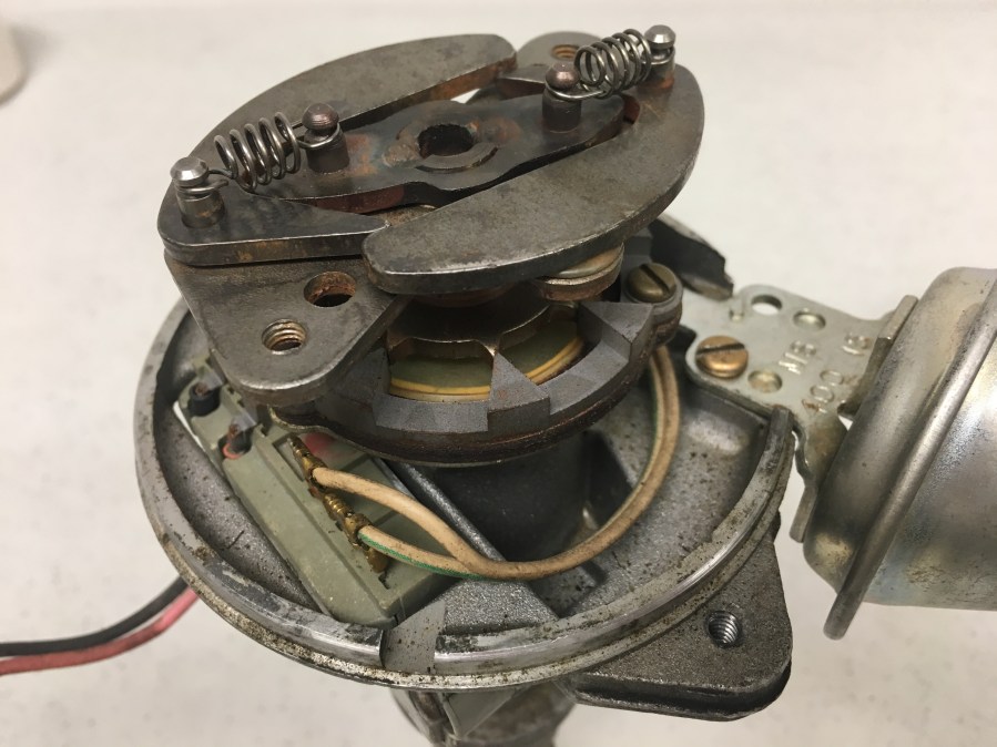
Close-up views of system:
Module
Coil terminal ID:
Wiring hookup:
Exposed terminal is convenient hookup for TACH
12-volt power hookup:

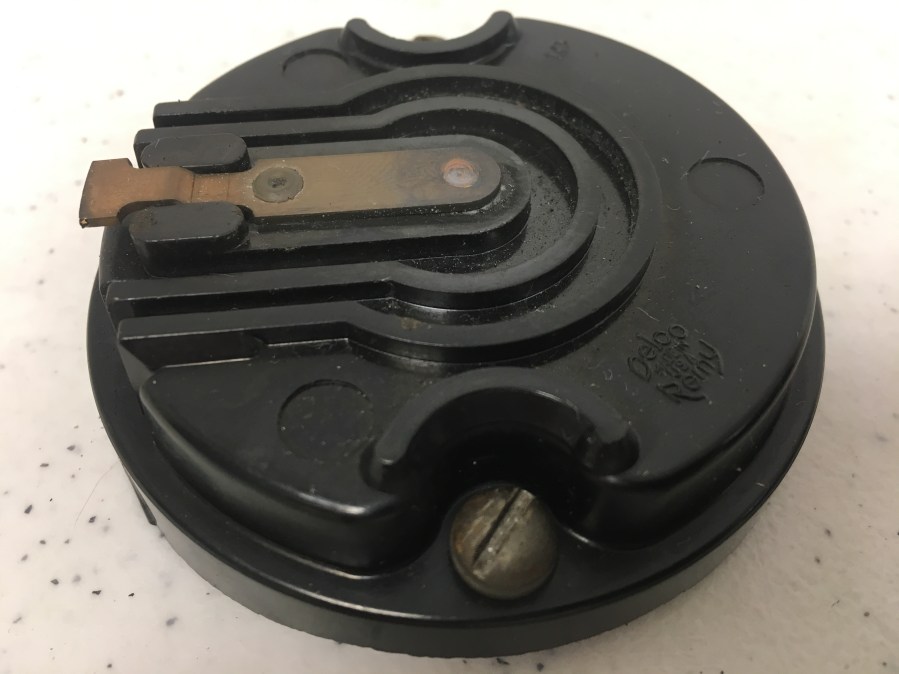
Rotor (similar to standard rotor except the segment is basically flat):
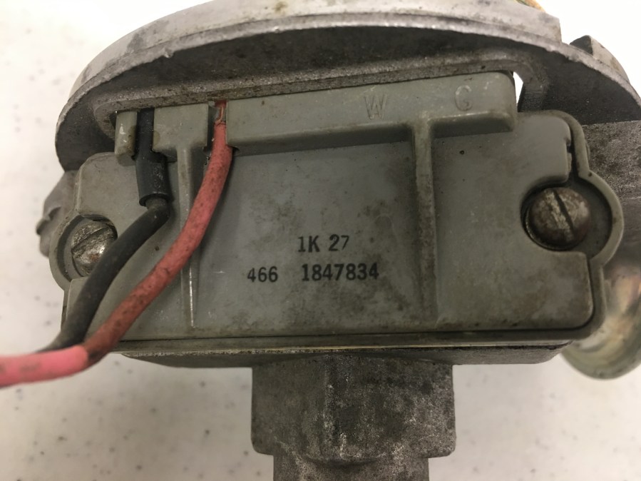
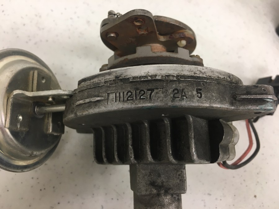
Closeup of part number/ date code stamping (January 5, 1972):
The unitized ignition system was short lived, but as you can see it was an obvious transition product between earlier systems and the soon to be introduced HEI system!
F) HEI System
The HEI (High Energy Ignition) System was a revolutionary ignition system developed by Delco Remy.
Developmental progression of HEI module design:

Close up of very early development HEI module:

Interesting that these developmental modules already carry the 1875990 production part number. This part number would remain in use for years to describe the typical 4-terminal HEI module. These early modules have 5 terminals because the ground is still separate. Soon it would be integrated into one of the mounting lugs:

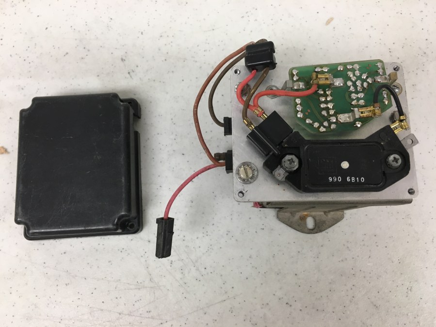
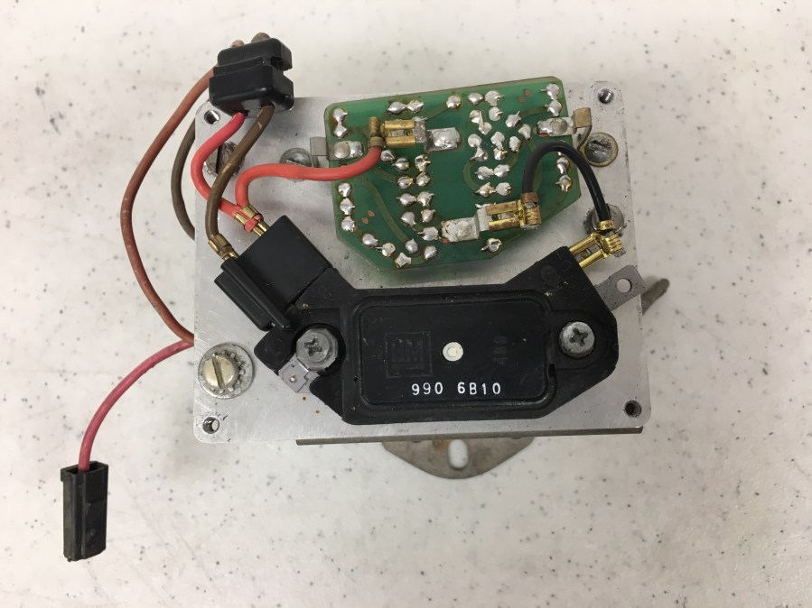
Revisions and improvements of production HEI modules over time. This module was referred to internally as the “990” module, and eventually the beginning of the part number was left off in production, leaving just the 990:

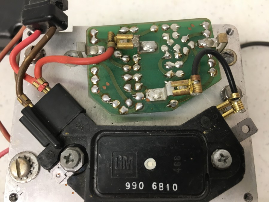
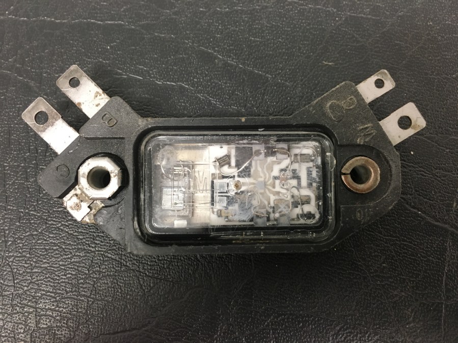
Final design of “990” HEI module with transparent cover showing micro-electronics:
Revisions of original “990” module for other applications not requiring as much output as the original V8 engine applications:

More info coming!!
